The wooden footbridge across the Jubilee River at Mill Lane has failed. Two vital structural members are broken and the bridge is now very weak so please don’t try to use it.
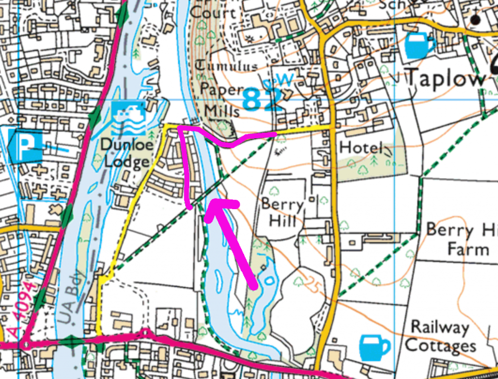
This map shows the location of the bridge and how you can easily avoid it on foot and by bike:
What has failed?
Here is the south-east side of the bridge. You can see that the top beam is bent and split:
Looking more closely there are two obvious failures:
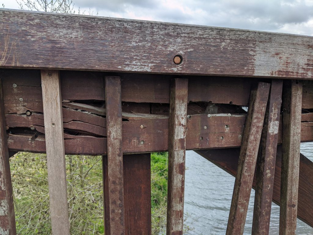
So we have one bent and split beam and one completely broken. One side of the bridge has dropped by about 100mm and it may still be getting worse. This is a serious bit of damage and it has weakened the bridge considerably.
Analysing Bridges
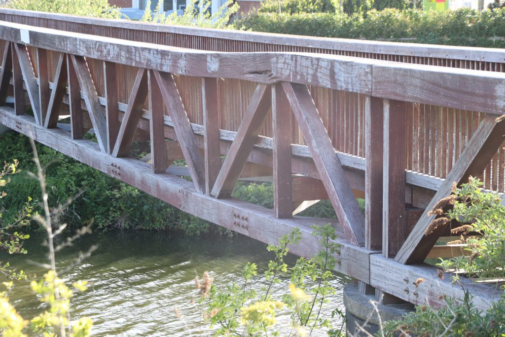
There are many different types of bridge and they work in different ways. This is a truss bridge, which means that it is a series of triangular sections working together. Here is the north face of the bridge:
You can see two spans in this picture. The left-hand span runs from the bank to the pier, and the middle span from the visible pier to another one hidden by the bushes on the right. Each span is completely separate: they are not joined together and they rest on the piers without applying any horizontal forces.
Most bridges are made up from components that are either in compression (being squashed from the ends) or in tension (being pulled from the ends). Here is a simplified diagram for part of our bridge:
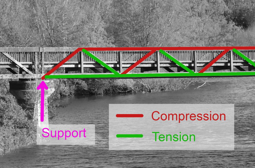
In this design the vertical members are mostly there to support the deck so the forces they carry are relatively small. The strength of the structure comes from the triangles: even if all the joints are pins (hinges) the truss will be rigid. In fact we could even replace all the green bits with wires and all the red bits with stacks of wooden bricks and it would still work (until the wind blows, but that’s another story)!
An engineer designing a bridge like this would now start setting up systems of simultaneous equations to make a mathematical model and would then calculate the actual forces and decide how big the beams need to be. Fortunately we don’t need to do all of that to get an idea of what happens if part of the structure fails.
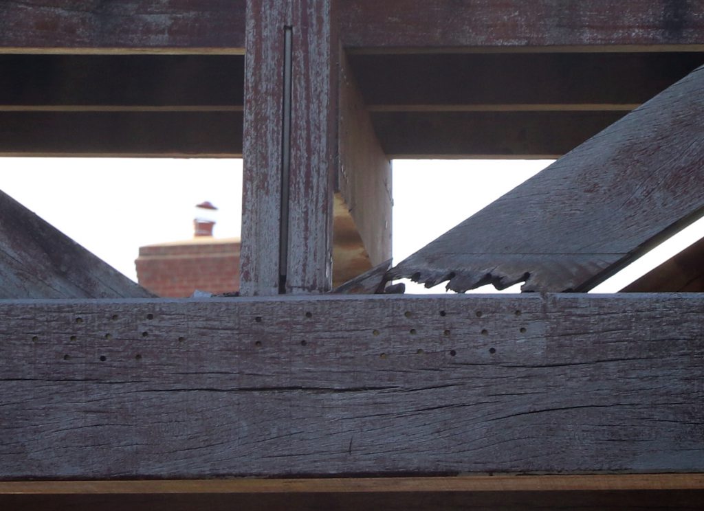
In our bridge, the root cause of the problem seems to be a rotten diagonal that has pulled out of its lower joint. That prevents it from carrying any load and we have lost two triangles:
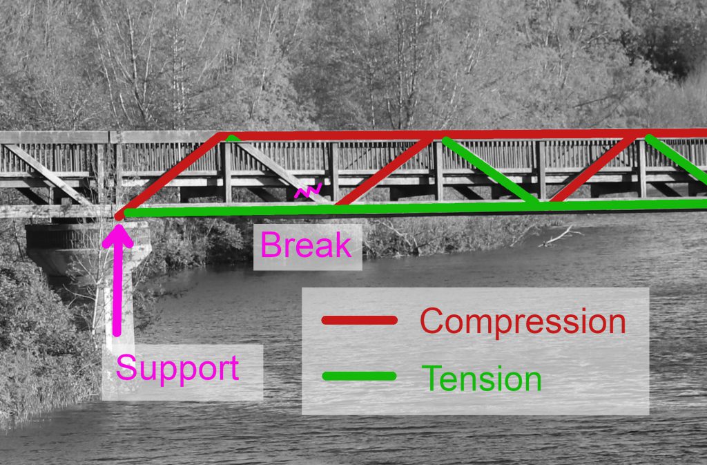
Now we have a parallelogram where we should have two triangles, and parallelograms with hinges at the corners are not much use! If this really were a simple pin-jointed structure it would instantly collapse into the river. Fortunately there are some other things there to hold it up. The first vertical is now in tension but it was not designed to be, and its top joint is not strong enough so it has pulled the top beam apart. What we are left with is a mess: some members have bending loads, some are twisting, and the forces in others may even have reversed. It is well beyond my ability to analyse and it certainly isn’t safe!
Repairing the bridge
So what next? This bridge was originally assembled on flat ground and lifted into place with a big crane. Ideally we would use the same process to remove it for repair, but that is not so easy. The nearest road is some way away so getting a crane close enough will be difficult. Another approach would be to lift the whole span from underneath using a barge or floating pontoon. The problem again is access: there is a weir between this bit of the Jubilee River and the main Thames so our barge would have to be brought in by crane… Can we contrive some way to support the undamaged bit of the bridge while repairing it in-situ? How would you do it? It’s a puzzle, and it will be very interesting to watch what actually happens!
Andrew Findlay, May 2021